The Intelligent Ski-Course

Last year I started building an intelligent ski-course, which was basically a set of buoy drones that would swim to there positions in a public river to form a ski course. This would then allow tons of interesting possibilities such as easy setup and effortlessly changing the shape of the course. Most of the project is documented on hackaday.io. As I am a very eager slalom skier in dire need of a course I would very much like to finish this project. However, I find myself without time working on finishing my PhD. I will one day restart my efforts, if anyone is interested in developing the project from where I left it, you are more that welcome, just keep me in the loop.

The state of the project:

  1. Most of the code has been written.
  2. The electronics for the buoy and base station has been mostly finalized
  3. 3D printed parts needs to be revised
  4. Propulsion system needs to be tested

Birth of FEMU 2.0

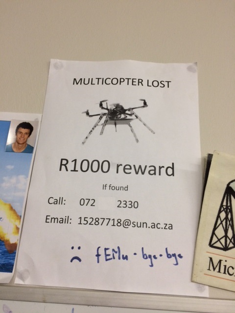
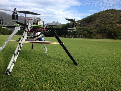
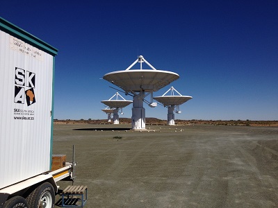
As part of my PhD research, involving the characterisation of the propagation environment at the SKA Karoo, time was spent developing a multi-copter RF metrology vehicle. A dramatic autopilot failure in our early prototype caused a the multi-copter to fly away forever. This event gave us a clean slate to do a full redesign upon what we have learned. One of the main problems with RF metrology using a multi-copter is the effect of the multi-copter itself on the measurement, which at this point has not been adequately addressed in research. Therefore, we set out to design a vehicle that could be appropriately de-embedded from a measurement.

The performance of antennas onboard these vehicles are in most cases unknown or assumed. These antennas have a specific characteristic pattern which could cause significant fluctuations in the measured signal, depending on its orientation. Even if the orientation was kept constant, the antenna patterns are sensitive to changes in metallic structures of the vehicle. An excellent example of this is the replacement of batteries after a flight. The replacement battery might have slightly different dimensions, position and will most certainly perturb some of the ubiquitous wires in the system.

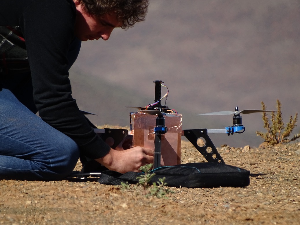
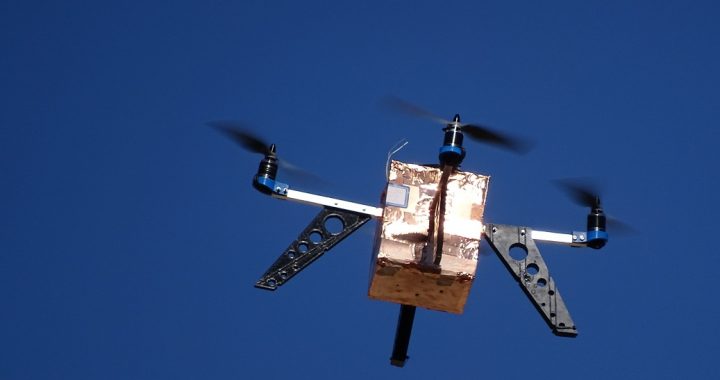
Our approach was to shield all of the subsystems of the vehicle in a metallic enclosure. This shielding gave us a platform which had a predictable antenna pattern. Also, by closing the complex metallic environment, accurate antenna simulations have been made possible. Additionally, FEMU 2.0 also boasts a quasi-isotropic antenna pattern and a bandwidth of 260 MHz to 960MHz (See the paper for more information on this).

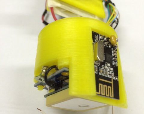
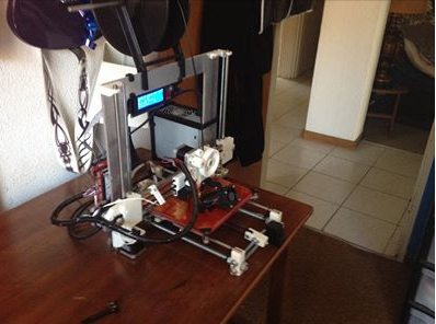
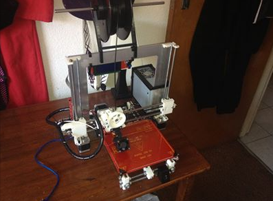
Hopefully, this will pave the way for RF metrology using multi-copters. If done correctly this could significantly speed up measurement time and deliver measurements that are spatially continuous. The entire vehicle has been constructed from 3D printed parts and local hardware supplies. The electronics, receiver and antenna systems can all be made available if another research group is interested in further developing the project.

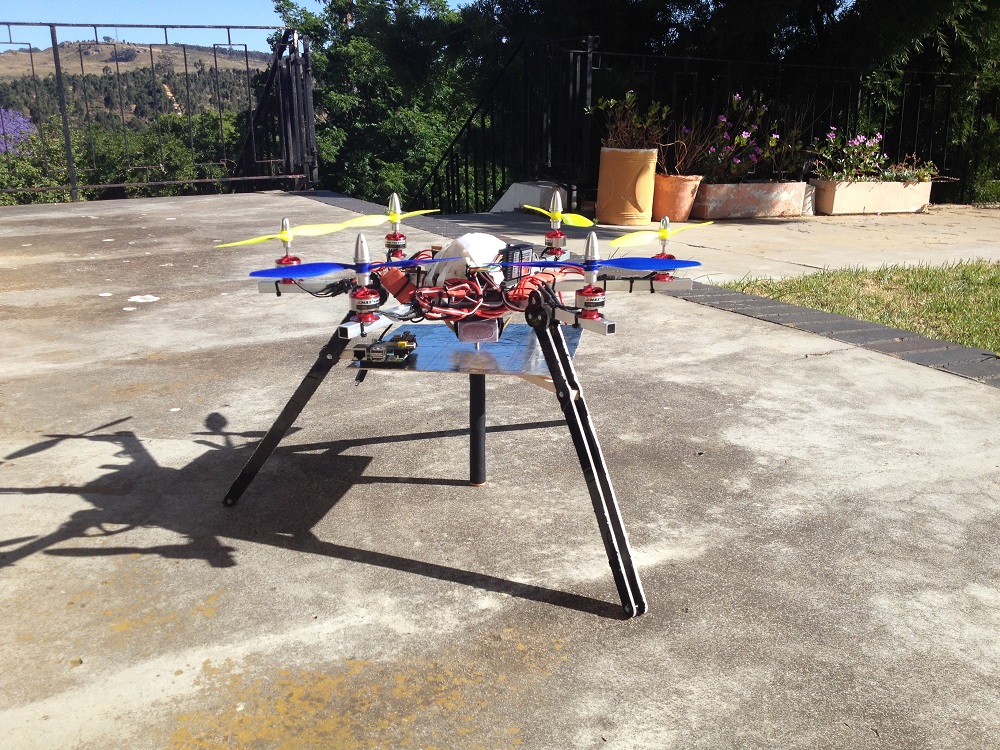
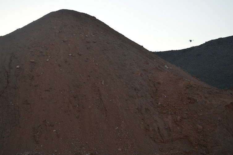
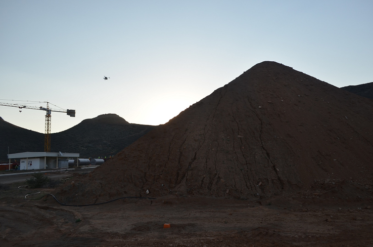
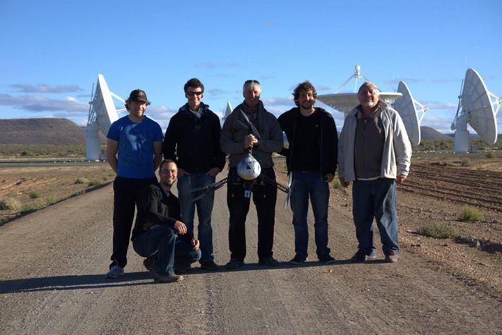
Below are two images showing FEMU 2.0 during setup and measurement.

Setting up FEMU 2.0 before flight


Don’t Leave Me…

Since the last post, we have completed a year of successfully RF measurement campaigns. Sadly, the quadcopter featuring in the previous post (FEMU 1.0) underwent an autopilot failure during a measurement dry-run which caused it to fly straight up into the air until its battery died. It has never been seen since. This forced us to build FEMU 1.5 in 3 days. Being a temporary vehicle, FEMU 1.5 was decommissioned shortly after his first measurement campaign (25 flights). All this happened in the earlier part of the year and gave us the opportunity to do a complete redesign which will be discussed in the next post. This redesign formed a large part of my PhD degree and made attempts to break new ground in RF metrology using Multicopters.

Reward if found poster for the disappearance of FEMU 1.0

Reward if found poster for the disappearance of FEMU 1.0

This was also the start of our quest to 3D print antennas, see the 900 MHz antenna mounted at the bottom.

FEMU 1.5 with a 900 MHz antenna

FEMU 1.5 with a 900 MHz antenna

Python in Eclipse

A short brief walk-through on setting up a python environment in Eclipse with the necessary libraries. Note that all installers need to be of the same architecture namely 32bit or 64bit. This walktrhough will focus on the 64bit case.

1. Install the latest java runtime environment

2. Install the latest python distribution

3. Install the latest eclipse environment

4. Follow the instructions on the pydev site to install and setup the pydev module

5. Install the fundamental libraries from this site, below is a list of packages I would recommend:

  1. SciPy
  2. Numpy
  3. Matplotlib

I would recommend looking for the latest versions of the linked applications.

My 3D Printer

I decided it would be a good idea for our lab, and for me, to have a 3D printer at our hands. After some consideration, I ordered a kit from a local supplier DIY Electronics whom I would gladly recommend. The kit, a relatively new design, is named a Prusa i3. Up to now, after the printer has been assembled and improved. I have yet to decide on a proper name.

Below is a very crude time lapse I made using my GoPro 3, suction-cupped against the wall.

After installing the Repetier host and firmware and getting the end stops and motors working in the correct directions I was able to successfully print a cube. Which I thought was way too easy. After some numerous calibration guides and models from Thingiverse I have calibrated my machine enough to print its own parts. The list of which I will share at the end of this post. He was originally just white, but now has a few black parts which were all self-printed with PLA.

printer2

MG at Langebaan

Here is the MG close to our favourite kite-boarding spots Langebaan and Shark Bay. This was taken at the mill house close to the local Club Mykonos casino.

img_1761

RFM22B on a Raspberry Pi

After about 3 weeks the Raspberry Pi RFM22B has arrived. The boards have been soldered and tested. There is some setup needed to get the SPI interface working, this is all explained at the top of some example code I am attaching at the bottom of this post. I built a total of 3 of these boards, each with a differently tuned RFM22B board. These boards are being used on my Quad copter as a small lightweight spectrum analyzer. I have attached both the code that I am currently using to drive the modules as well as a .zip file which can be directly submitted to Oshpark for fabrication. If you manage to try it, let me know how it works for you. The code I have written at the moment only covers setting the frequency, IF filter and pre-amp and allows the programmer to request the current RSSI level. I have also attached a LED which is directly connected to the GPIO pins just to play with.

Board mounted on GPIO port of Raspberry Pi

Board mounted on GPIO port of Raspberry Pi

Python driver code

Fabrication files

Schematic

Schematic

32 bit spectrum analyser update

The 32-bit spectrum analyzer has been used for multiple tasks in its prototype form. However, it has been decided to slightly change the final design. This choice is motivated mainly by the application I am using for my Master’s degree. Therefore, this is the end of the development for the 32-bit analyzer and the birth of the raspberry-pi analyzer. The specification will be much the same as previously listed, however, the micro-controller will be replaced with the raspberry pi which will communicate directly to the RFM22B chip via its own SPI channels. The software will all be written in python and will have much the same functionality as my current 32bit spectrum analyzer design.

In the meantime, I will attach the MPLAB project file and python source code used to interface with the device below. The MPLAB project file clearly lists the pin allocations which eliminates the need for a schematic. Finally, see the board layout for the raspberry pi spectrum analyzer board ordered from OSHPark.

Top and bottom board layout of new raspberry pi spectrum analyser

Top and bottom board layout of new raspberry pi spectrum analyser

MPLab project for 32 bit spectrum analyser

Python interface code for host PC

Note that this was not by far a final design of the code, there are still many small bug fixes and streamlining needed, for example, the communication protocol between the device and host still needed to be sent bytewise and not by character, however, feel free to use it for experimentation. Below is a photo of the 32 Bit spectrum analyzer measuring a sweep with a resistively loaded monopole antenna built by my colleague, Matthew Groch.


New Set of Legs for SKA Measurements…

With a lot of help from a friend, Johan Frank, new legs and a platform was built for the quad copter. These legs allow for an antenna to be mounted below a platform supporting a spectrum analyzer and single board computer. This platform was specifically built for a measurement campaign at the SKA site which turned out very successful.

img_2319

RF Propogation Measurements Over a Berm with the Use of a Multicopter

The RF shielding effect of a berm was measured using a Multi-copter as part of my PhD program. LS of SA from LS telecom generously helped us with these measurements with their own Multi-copter measurement platform. The measurements were done with a transmitter located on the far side of the berm transmitting 9 vertically polarized frequencies, from 60m, directly at the berm. Below is a photo of the Multi-copter measuring in the vicinity of the berm.

Far side of berm, opposite side than transmitter

Far side of berm, opposite side than transmitter

Front side of berm, same side as transmitter

Front side of berm, same side as transmitter

The data was then processed and compiled together from a total of 7 10 min flights at different heights and configurations. The processed data was plotted and interpolated with python on a 2D grid with an overlay of the berm. The next 3 clips shows animations of the interpolated data over different frequencies and heights.

Final Word

I would just like to thank the measurement team and especially LS of SA for the great collaboration.

group photo

From the left:
Mathew Groch: Responsible for broadband loaded dipole antenna used in these measurements
Jan (crouching) from LS of SA
Nardus Mathyssen responsible for developing a pulse generator which will be used in future measurements
Wessel from LS of SA
Myself Hardie Pienaar
Brian from LS of SA