Assembly of Power, Sensors, and Communication…

Before being able to do some wireless tests, the sensors and telemetry radio need to be powered. In this first phase of assembly, the power distribution board, IMU board along with the telemetry was mounted on the frame. Thereafter a single electronic speed controller was connected to power the IMU board and radio. As of now, the quadcopter is fully wireless and self-powered.

assphase1

Motorless self powered quadcopter


Graphical User Interface v1…

Here are some screenshots of the spectrum analyser graphical user interface. Please note that the levels shown have not yet been tested with proper equipment. Proper tests and calibration will be done in the next hardware iteration.

Spectrum profile of a car remote

Spectrum profile of a car remote

Spectrum profile of a FSK 12.5kHz Trunking Control Channel

Spectrum profile of an FSK 12.5kHz Trunking Control Channel

The Compass…

Another sensor needed during navigation and control was added to the IMU board. This sensor, a magnetometer, is responsible for measuring the orientation using the earth`s magnetic field. In a plane setup, the current heading can be easily determined by making use of consecutive GPS measurements.  On the other hand, a quadcopter does not need to stay moving all the time and therefore needs a sensor that is able to measure its heading while hovering.

The compass is mounted to an I2C channel on the top of the IMU board. Seen as a small extra daughter board. Running the mission planner command line interface some data was gathered to prove that the compass is functioning correctly.

Command Line Interface magnetometer test data

Command Line Interface magnetometer test data

GPS Take 2…

A new GPS arrived today, all the way from 3DRobtics, as a replacement for my previously dead on arrival GPS unit. This time around the GPS worked as soon as it was plugged in and even started acquiring satellites from indoors.

RS232 Spectrum Analyser

This project came from the idea that I needed a simple, light spectrum analyzer which could be easily interfaced to embedded applications. This design was a proof of concept which made use of an RFM22B radio module and a PIC16F690. A simple GUI was also constructed for initial testing purposes. Photos of the prototype can be seen below. Source code for the proof of concept can be found downloaded here:

Visual C# Project

MPLab Project

Pic kit 2 Logic Analyzer tool output for a SPI command to the RFM22B

Pic kit 2 Logic Analyzer tool output for a SPI command to the RFM22B

The next post will contain some screen shots of the GUI in action.

The Telemetry…

For this project a constant data communication will be needed from the vehicle and its payload to a ground station. Therefore, a telemetry radio needs to be present. Fortunately, the APM 1 kit discussed earlier makes provision for a telemetry module. The telemetry modules I opted for was from 3DRobotics running at 433MHz 100mW. Due to ICASA regulations, these radios can only be used at 8mW maximum. This should be more than enough.

The Flight Controller…

The flight controller is the brain of the vehicle and will contain most of the essential sensors.  To save time I opted for a Ardu-Pilot Mega 1.0. The main reason why I opted for the 1st generation and not the newer second generation is to have the option of replacing the 8 bit micro-controller with a 32 bit variant in the future.

Assembly of the APM 1.0 kit was rather easy, but took a while to solder all the connections. Hereafter, the flight controller was connected to its Mission Planner software, which confirmed proper working of the gyros, accelerometers and barometer. With some dismay the kit did not come with the magnetometer and will therefore still need to be acquired and tested later on.

One disappointment, however, was that the Mediatek GPS that came with the kit was dead on arrival. When connected to the APM board the 3D fix blue light came on and stayed on while the mission planner displayed no GPS. When going into the command line interface of the mission planner to test->GPS the only output was a constant string of G!G!G!G!. After confirming all connections from the GPS module on the adapter to the micro-controller as well as a 3.2V output on its regulator I used a FTDI cable to directly communicate with the GPS module. Hyper terminal showed that there was no data coming from the module itself. Thereafter I tried flashing the module with its own software which kept giving me a BROM_CMD_START_FAIL error. Luckily Carmen at 3DRobotics offered great support and shipped another module immediately.


The Frame…

The NXF-4 frame was bought from Netram in Durban (now in Cape Town), South Africa. It took 24 hours from order to delivery which I was quite impressed with. After it was delivered it took me a couple of hours to assemble with some spare parts. All in all the frame feels sturdy and has an interesting colour scheme. I will, however, be exchanging all of the nuts with some more reliable lock-nuts.

Energy waster (Final year project)

This was my final year project for my BEng degree. The idea for this project came from the problem that certain South African prepaid meters bill the residence for the power they generate into the grid. This project investigated a temporary workaround for this problem, by diverting the net outflow of power into a resistor bank, the extra cost would then be minimized. This project consisted of some simple power electronics, C programming for the micro-controller and some electronic system design.

Energywaster4

Energywaster3 Energywaster2 Energywaster1


SCADA for Windtunnel Project

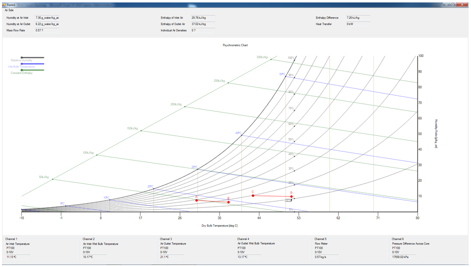
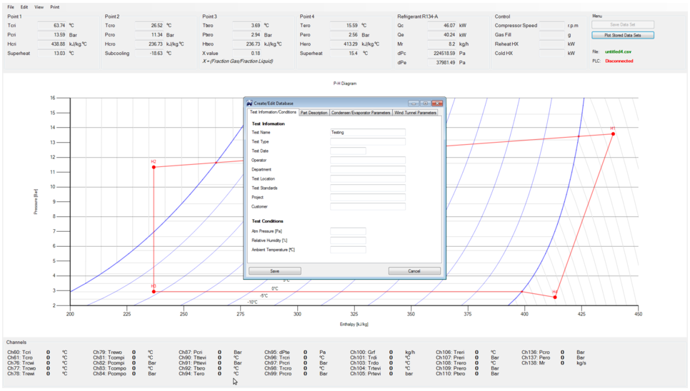
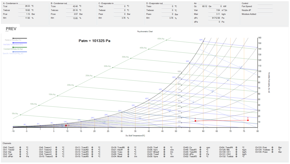
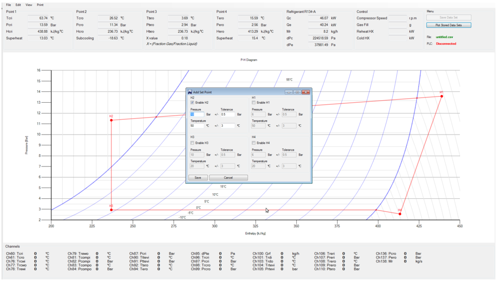
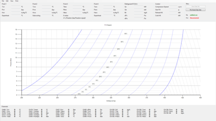
This project was done by myself for a company called TFDesign, the software is in phase 1 at the moment and is capable of reading data from a Siemens PLC, processing the data with some thermodynamic libraries and finally plotting the data on a psychometric and pressure-enthalpy graph. The software has extra functionality such as the saving of points, saving the current workspace and fading points to show the trend of the graphs. This project was written in C#. This project, however, is not open source, so I can only offer screenshots.

The project software has the capability to set certain “set points”, save current data as well as generate performance plots with the saved data. The set points is for the user to know where he wants the data points to move to. When at these certain set points the user can save the data to be later used in generating performance plots. The software starts on 2 HD resolution screens and immediately starts plotting the data read from the PLC.

psychrometricChart

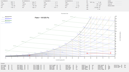
Here are a few more screenshots. This was my first big commercial programming project which turned out quite well. The program is still in use at 2 facilities and has been handed over to the company for small updates and maintenance.


Windtunnel1 Windtunnel2 Windtunnel3 Windtunnel4