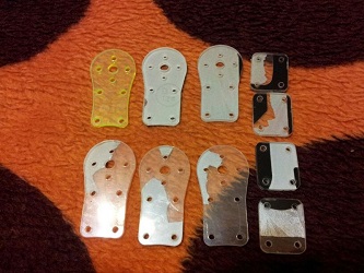
After flying in loiter mode for a while the quad-copter suddenly flipped over. I immediately switched to Stabilize mode and increased throttle in an attempt to save the situation. It stabilized itself just before hitting the ground but sadly had too much horizontal velocity. As a result, the quadcopter snagged and rolled in spectacular fashion. The damage was two motor mounts and a landing gear. The cause of the flip: bad connection to one of thESC’s’s from the APM 2.5 output.
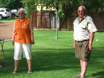
In the beginning of 2011 my grandfather gave me his 1968 MG midget MK III. The car is still in almost perfect condition as can be seen in the photo taken in Stellenbosch. I will dedicate this part of my webpage to give updates on my MG. The bottom photo shows my grandmother and grandfather playing bowls.
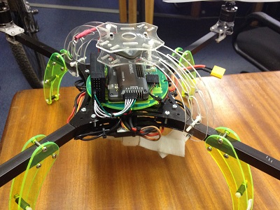
Upgraded to the APM 2.5. Height and GPS accuracy are significantly better than the APM 1.0. The APM 2.5 also has a much higher telemetry data throughput due to some of the signal processing happening off of the Atmel chip. Below is a photo of the new neat setup containing the APM 2.5.
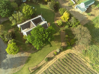
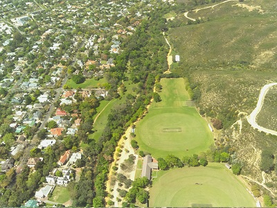
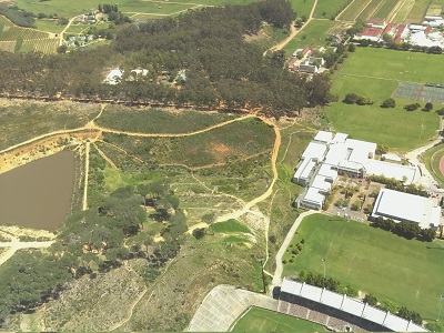
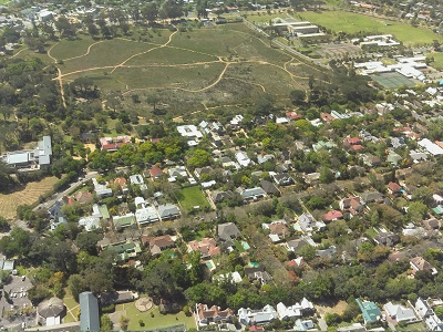
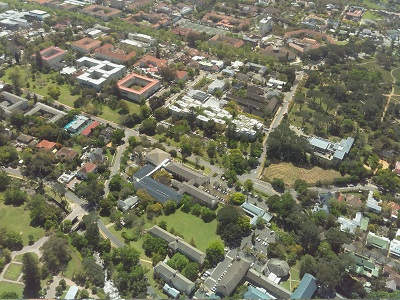
After receiving my raspberry pi camera, I thought it to be a good idea to take some aerial photos with the quadcopter. The first few photos are from Stellenbosch University campus followed by the last few which are from a farm near Worcester, South Africa.
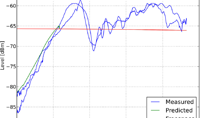
After getting the quadcopter to fly in loiter and auto missions with confidence, it was decided to use the quadcopter for measuring RF signal propagation. This measurement was done with a transmitter on one side of a 13m high human-made berm. Flying a vertical path up to 50m on the far side measuring the diffraction of the continuous wave signal at 400MHz. Below is a video with the payload strapped to the quadcopter, note that the antenna (yellow block) was exchanged for a small stub antenna during the actual measurement. The measurement was done using my RS232 spectrum analyser logging onto a Raspberry Pi. The effect of the quadcopter on the antenna pattern was ignored, and the measured data were treated as relative. The measured data can be seen in the featured image and resembles a diffraction pattern. This pattern has been verified against some prediction code of a colleague. As a first test, this proved very successful as a proof of concept and was hereafter named fEMu (flying Electromagnetic Metrology unit).
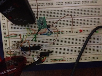
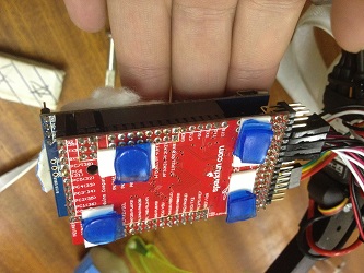
It is time to revisit the RS232 spectrum analyser. Below is an image of some prototyping on a breadboard followed by a soldered working version including an SMA connection. The problem with the previous spectrum analyser was mainly in the computation of the frequency set registers which involved large 9 digit values, a hard feat for an 8-bit microcontroller. This time around a 32-bit microcontroller, the PIC32MX220B032 will be used. This will allow for a maximum clock frequency of 50MHz leaving the radios internal frequency settling time as the only limiting factor to the spectrum analyzer sweep time. The proposed specification for this spectrum analyzer is as follows:
Bandwidth 260MHz – 960MHz (Realistically about 150MHz according to the input filter of the RFM22B model used)
2ms per sample
Sweep and Discrete measurement modes
Calibration mode (Calibrates the device with the help of a sweeping signal generator)
Wireless trace measurement (Two devices needed, one as a base station)
SD card for onboard storage and buffering
Connectivity – FTDI cable and rasberrypi GPIO connector header
Form factor: 1 square inch
Breadboard prototyping of the 32bit spectrum analyser
After the vibration issues were sorted out it was time to test the loiter and auto modes. A video of the first successful loiter test can be seen below. The APM 1.0 seems to hold its position reasonably well given that there was a slight breeze that day. The quad-copter was also instructed to land in loiter mode. The video was taken behind our engineering building at Stellenbosch University. We have also tested the auto mission, takeoff and landing successfully.
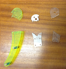
The new motor mounts were made by Johan Frank from Malmesbury on his own CNC machine with simple number-plate plastic. These new motor mounts are much less brittle and therefore much stronger than the original perspex parts.
After the quadcopter was fully assembled including ESC’s, accelerometers and radio calibrated it was ready for its maiden flight. This flight was carried out at the back of our Engineering building, Stellenbosch, on an insufficient piece of grass. A short video from the flight can be watched below.
After some time flying the altitude hold function was tested which seemed to work. However, when testing the second time and switching it off, the throttle was in a lower than hover position, causing the quad to come down hard. This caused three perspex motor mounts to be snapped off. Luckily this exposed some weaknesses in the frame. The motor mounts will now be manufactured from a slightly less brittle plastic. Ignoring human error (first ever flight) the quadcopter flew excellent the first time.
After a number of flights in stabilize mode with a very stable vehicle, it was decided to test the rest of the flight modes. Our goal was to build this into a measurement platform which necessitates the use of the auto modes. Therefore, we went to an open test field near Stellenbosch where we switched the quadcopter to loiter mode. The latter action caused the quadcopter to ascend at full throttle with no sign of stopping. After landing and trying again the same thing happened.
After this slightly unsuccessful test, I learned that in the newer APM firmware versions vibration can be an issue and can cause the observed behaviour. I decided to start eliminating all the vibration I could find. Starting with the motors I measured the vibration with an app called “vibration on my iPhone”. Spinning each motor independently while strapping the phone onto the motor arm I could monitor the intensity of the vibration and start balancing the motors in the same manner as the video I found below.
After some experimentation, I realized that the motors without any nut and spinner were perfectly balanced, however, as soon as the spinners are added it would put the motor extremely off balance. As a result, I balanced each spinner with a piece of tape, much like they balanced the motors in the video. This meant I now had 4 non- vibrating motors. At this stage, I did not have a prop balancer and had to hope my cheap colourful gem-fan propellers were reasonably balanced.
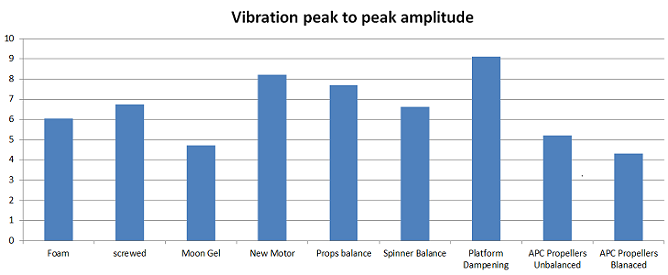
To actually test if there were any relative improvement I enabled the IMU data logging onboard the APM. I downloaded the log after each change to relatively measure what performance difference the modification had.
It can be seen in the comparison that there was initially also some experimentation with different APM mountings such as being screwed down, double-sided tape, moon gel pads and lastly, the configuration that is still being used, dampening pads below the entire electronics platform. Remember that these modifications were done before balancing the spinners, note that it almost seems as if the vibration got worse with the different platforms except the moon gel. It should also be stated that with the new dampening pads the whole layout of the vehicle was changed. A motor which was slightly damaged in the previous crash was also replaced with more negative results. However, balancing the prop spinners and propellers showed a slight decrease in vibrations as seen in the graph below. Something weird was noticed when balancing the gemfan propellers, it seemed that they would be heavier on one side of the hub. It was here that I decided to invest in more expensive APC propellers which as you can see made a huge difference and finally enabled loiter and the auto modes to work flawlessly.
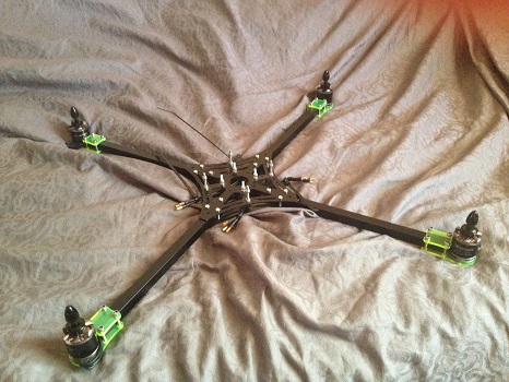
After a long break moving to another city, I restarted my efforts on the quadcopter build. This time adding the motors and finalising the construction to the point of a maiden flight. Some changes to the previous thought process were incorporated: channelling the high current ESC wires through the aluminium tubes. The latter meant disassembling the whole quadcopter.
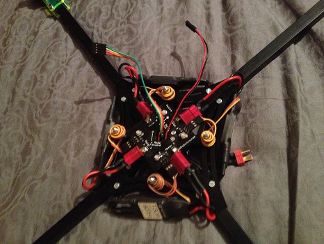
The motors are 800kV tiger motors which will each, in turn, need to drive a 10×4.5inch prop. The motors can be seen mounted on the edges of the quadcopter with their cabling running through the aluminium tube into the centre plate cavity. Next, the power distribution board was fastened on top of the centre plate with the help of plastic screws. This allowed the ESC’s to be installed connecting all four motors allowing some initial testing. To test the motors, the battery and PWM lines were connected to the distribution board and receiver module respectively. After confirming all four motors are spinning their directions could be set as illustrated in the APM wiki. The connections for the power distribution board can be seen below. The ESC PWM wires will need to be shortened, in the current configuration they will cause horrific RF pickup loops.
ESC’s and PDB mounted
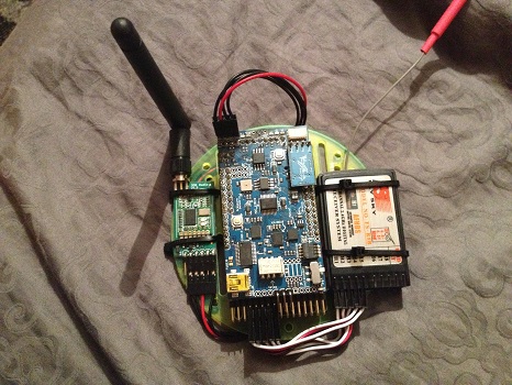
With power and PWM connections to the motors now established the remaining electronics can be added to the build. The APM, telemetry radio and receiver are all now mounted on a platform and connected. This platform is part of the frame and will fit right above the distribution board. The electronics platform can be seen below.
Assembled electronics platform
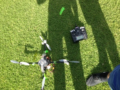
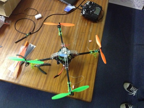
After the electronics platform has been fitted, the shell containing the GPS and the landing gear was attached. Before mounting the props the ESC’s needed to be calibrated, which on stock settings were remarkably different from one another. Due to some physical restrictions, the quad is currently configured in a plus orientation which might be changed in the future. The quadcopter with its props can be seen below next to its 9x FrSky remote.