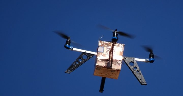
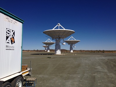
In the past few years, FPV racing has quickly grown into a competitive sport. As a result, it has become necessary to keep track of lap times. Time-keeping is usually done using IR transmitters and receivers. However, this timing can be done without adding extra IR or RF beacons. By making use of the already present video transmitter on each vehicle, it is possible to keep track of every everyone in the race using their specific video channel frequency. However, there are some problems associated with using the 5.8 GHz emissions to track the vehicles. The first is the spatial accuracy where a timing event is triggered; the second is the effort needed to monitor the full FPV RF band continuously. The first problem in realising such a system is to design the receiving antenna.
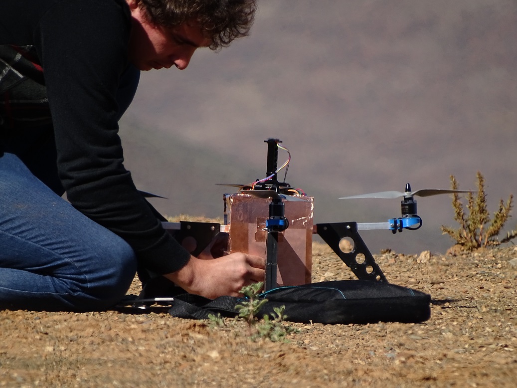
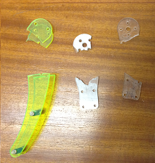
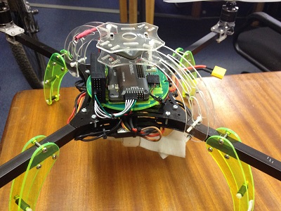
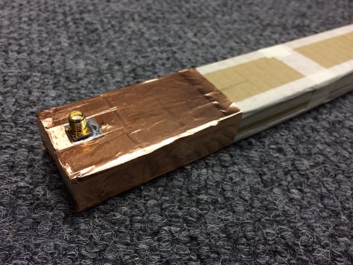
A straightforward and cheap solution exists for the antenna. Using some cardboard, foil and aluminium or copper tape it is possible to build a high-gain waveguide antenna at 5.8 GHz. A slotted waveguide antenna has a thin disc shape antenna pattern which is ideally suited for use as a timing gate. Below are some photos showing the construction of the antenna.
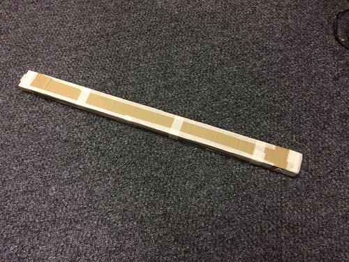
Cardboard structure
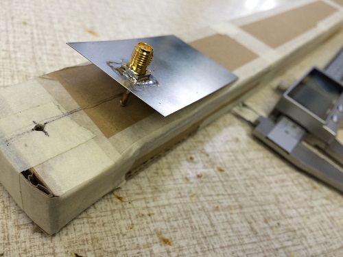
Adding the feed structure
Feed in place
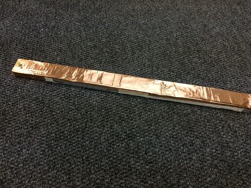
Wrapping the rest of the waveguide in foil
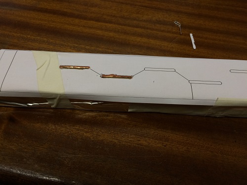
Cutting waveguide slots
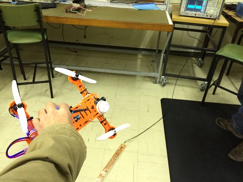
Testing the antenna
The receiver needs to be broadband to be able to monitor all of the vehicles at the same time. For this, I would suggest mixing down the antenna signal to below 1 GHz and use multiple RTL-SDR dongles as a low-cost solution for monitoring all of the multi-copters in real-time.
Unfortunately, I have run out of time to work on the receiver. I will upload further data if there is interest in reproducing the antenna or continuing the project.