After the vibration issues were sorted out it was time to test the loiter and auto modes. A video of the first successful loiter test can be seen below. The APM 1.0 seems to hold its position reasonably well given that there was a slight breeze that day. The quad-copter was also instructed to land in loiter mode. The video was taken behind our engineering building at Stellenbosch University. We have also tested the auto mission, takeoff and landing successfully.
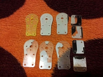
The new motor mounts were made by Johan Frank from Malmesbury on his own CNC machine with simple number-plate plastic. These new motor mounts are much less brittle and therefore much stronger than the original perspex parts.
After the quadcopter was fully assembled including ESC’s, accelerometers and radio calibrated it was ready for its maiden flight. This flight was carried out at the back of our Engineering building, Stellenbosch, on an insufficient piece of grass. A short video from the flight can be watched below.
After some time flying the altitude hold function was tested which seemed to work. However, when testing the second time and switching it off, the throttle was in a lower than hover position, causing the quad to come down hard. This caused three perspex motor mounts to be snapped off. Luckily this exposed some weaknesses in the frame. The motor mounts will now be manufactured from a slightly less brittle plastic. Ignoring human error (first ever flight) the quadcopter flew excellent the first time.
After a number of flights in stabilize mode with a very stable vehicle, it was decided to test the rest of the flight modes. Our goal was to build this into a measurement platform which necessitates the use of the auto modes. Therefore, we went to an open test field near Stellenbosch where we switched the quadcopter to loiter mode. The latter action caused the quadcopter to ascend at full throttle with no sign of stopping. After landing and trying again the same thing happened.
After this slightly unsuccessful test, I learned that in the newer APM firmware versions vibration can be an issue and can cause the observed behaviour. I decided to start eliminating all the vibration I could find. Starting with the motors I measured the vibration with an app called “vibration on my iPhone”. Spinning each motor independently while strapping the phone onto the motor arm I could monitor the intensity of the vibration and start balancing the motors in the same manner as the video I found below.
After some experimentation, I realized that the motors without any nut and spinner were perfectly balanced, however, as soon as the spinners are added it would put the motor extremely off balance. As a result, I balanced each spinner with a piece of tape, much like they balanced the motors in the video. This meant I now had 4 non- vibrating motors. At this stage, I did not have a prop balancer and had to hope my cheap colourful gem-fan propellers were reasonably balanced.
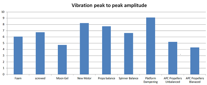
To actually test if there were any relative improvement I enabled the IMU data logging onboard the APM. I downloaded the log after each change to relatively measure what performance difference the modification had.
It can be seen in the comparison that there was initially also some experimentation with different APM mountings such as being screwed down, double-sided tape, moon gel pads and lastly, the configuration that is still being used, dampening pads below the entire electronics platform. Remember that these modifications were done before balancing the spinners, note that it almost seems as if the vibration got worse with the different platforms except the moon gel. It should also be stated that with the new dampening pads the whole layout of the vehicle was changed. A motor which was slightly damaged in the previous crash was also replaced with more negative results. However, balancing the prop spinners and propellers showed a slight decrease in vibrations as seen in the graph below. Something weird was noticed when balancing the gemfan propellers, it seemed that they would be heavier on one side of the hub. It was here that I decided to invest in more expensive APC propellers which as you can see made a huge difference and finally enabled loiter and the auto modes to work flawlessly.
After a long break moving to another city, I restarted my efforts on the quadcopter build. This time adding the motors and finalising the construction to the point of a maiden flight. Some changes to the previous thought process were incorporated: channelling the high current ESC wires through the aluminium tubes. The latter meant disassembling the whole quadcopter.
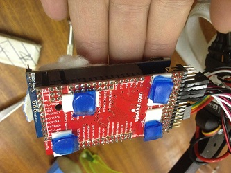
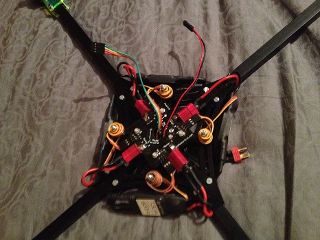
The motors are 800kV tiger motors which will each, in turn, need to drive a 10×4.5inch prop. The motors can be seen mounted on the edges of the quadcopter with their cabling running through the aluminium tube into the centre plate cavity. Next, the power distribution board was fastened on top of the centre plate with the help of plastic screws. This allowed the ESC’s to be installed connecting all four motors allowing some initial testing. To test the motors, the battery and PWM lines were connected to the distribution board and receiver module respectively. After confirming all four motors are spinning their directions could be set as illustrated in the APM wiki. The connections for the power distribution board can be seen below. The ESC PWM wires will need to be shortened, in the current configuration they will cause horrific RF pickup loops.
ESC’s and PDB mounted
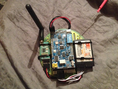
With power and PWM connections to the motors now established the remaining electronics can be added to the build. The APM, telemetry radio and receiver are all now mounted on a platform and connected. This platform is part of the frame and will fit right above the distribution board. The electronics platform can be seen below.
Assembled electronics platform
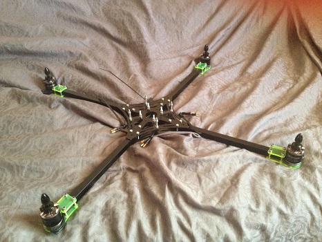
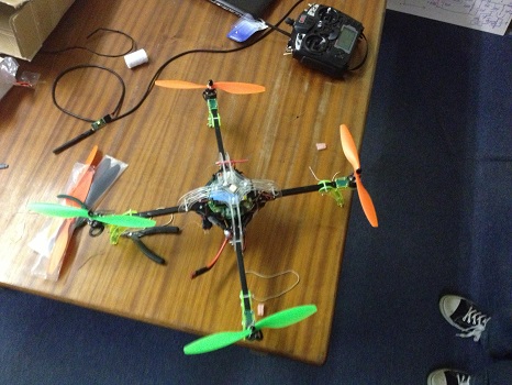
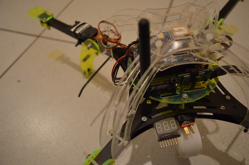
After the electronics platform has been fitted, the shell containing the GPS and the landing gear was attached. Before mounting the props the ESC’s needed to be calibrated, which on stock settings were remarkably different from one another. Due to some physical restrictions, the quad is currently configured in a plus orientation which might be changed in the future. The quadcopter with its props can be seen below next to its 9x FrSky remote.
Before being able to do some wireless tests, the sensors and telemetry radio need to be powered. In this first phase of assembly, the power distribution board, IMU board along with the telemetry was mounted on the frame. Thereafter a single electronic speed controller was connected to power the IMU board and radio. As of now, the quadcopter is fully wireless and self-powered.
Another sensor needed during navigation and control was added to the IMU board. This sensor, a magnetometer, is responsible for measuring the orientation using the earth`s magnetic field. In a plane setup, the current heading can be easily determined by making use of consecutive GPS measurements. On the other hand, a quadcopter does not need to stay moving all the time and therefore needs a sensor that is able to measure its heading while hovering.
The compass is mounted to an I2C channel on the top of the IMU board. Seen as a small extra daughter board. Running the mission planner command line interface some data was gathered to prove that the compass is functioning correctly.
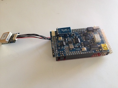
A new GPS arrived today, all the way from 3DRobtics, as a replacement for my previously dead on arrival GPS unit. This time around the GPS worked as soon as it was plugged in and even started acquiring satellites from indoors.
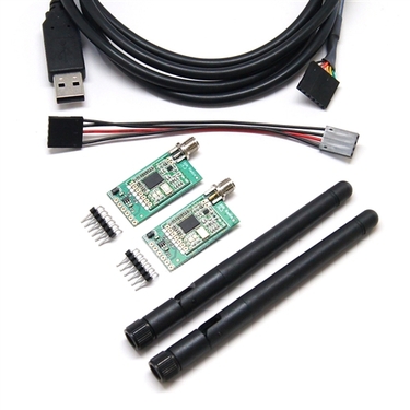
For this project a constant data communication will be needed from the vehicle and its payload to a ground station. Therefore, a telemetry radio needs to be present. Fortunately, the APM 1 kit discussed earlier makes provision for a telemetry module. The telemetry modules I opted for was from 3DRobotics running at 433MHz 100mW. Due to ICASA regulations, these radios can only be used at 8mW maximum. This should be more than enough.
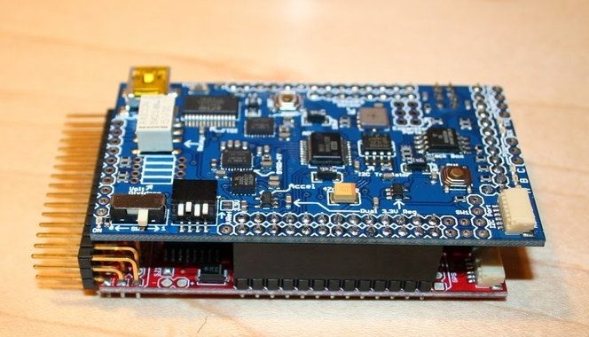
The flight controller is the brain of the vehicle and will contain most of the essential sensors. To save time I opted for a Ardu-Pilot Mega 1.0. The main reason why I opted for the 1st generation and not the newer second generation is to have the option of replacing the 8 bit micro-controller with a 32 bit variant in the future.
Assembly of the APM 1.0 kit was rather easy, but took a while to solder all the connections. Hereafter, the flight controller was connected to its Mission Planner software, which confirmed proper working of the gyros, accelerometers and barometer. With some dismay the kit did not come with the magnetometer and will therefore still need to be acquired and tested later on.
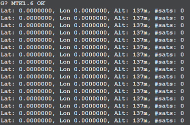
One disappointment, however, was that the Mediatek GPS that came with the kit was dead on arrival. When connected to the APM board the 3D fix blue light came on and stayed on while the mission planner displayed no GPS. When going into the command line interface of the mission planner to test->GPS the only output was a constant string of G!G!G!G!. After confirming all connections from the GPS module on the adapter to the micro-controller as well as a 3.2V output on its regulator I used a FTDI cable to directly communicate with the GPS module. Hyper terminal showed that there was no data coming from the module itself. Thereafter I tried flashing the module with its own software which kept giving me a BROM_CMD_START_FAIL error. Luckily Carmen at 3DRobotics offered great support and shipped another module immediately.
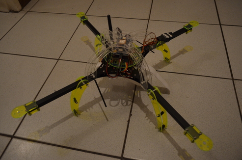
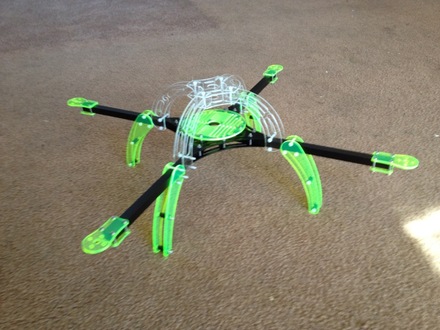
The NXF-4 frame was bought from Netram in Durban (now in Cape Town), South Africa. It took 24 hours from order to delivery which I was quite impressed with. After it was delivered it took me a couple of hours to assemble with some spare parts. All in all the frame feels sturdy and has an interesting colour scheme. I will, however, be exchanging all of the nuts with some more reliable lock-nuts.