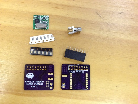
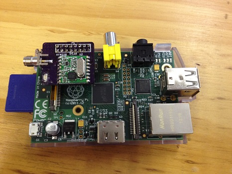
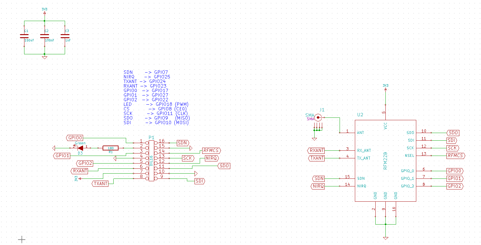
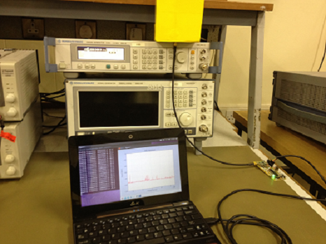
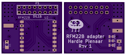
After about 3 weeks the Raspberry Pi RFM22B has arrived. The boards have been soldered and tested. There is some setup needed to get the SPI interface working, this is all explained at the top of some example code I am attaching at the bottom of this post. I built a total of 3 of these boards, each with a differently tuned RFM22B board. These boards are being used on my Quad copter as a small lightweight spectrum analyzer. I have attached both the code that I am currently using to drive the modules as well as a .zip file which can be directly submitted to Oshpark for fabrication. If you manage to try it, let me know how it works for you. The code I have written at the moment only covers setting the frequency, IF filter and pre-amp and allows the programmer to request the current RSSI level. I have also attached a LED which is directly connected to the GPIO pins just to play with.
Category Archives: RFM22B Spectrum Analyzer
32 bit spectrum analyser update
The 32-bit spectrum analyzer has been used for multiple tasks in its prototype form. However, it has been decided to slightly change the final design. This choice is motivated mainly by the application I am using for my Master’s degree. Therefore, this is the end of the development for the 32-bit analyzer and the birth of the raspberry-pi analyzer. The specification will be much the same as previously listed, however, the micro-controller will be replaced with the raspberry pi which will communicate directly to the RFM22B chip via its own SPI channels. The software will all be written in python and will have much the same functionality as my current 32bit spectrum analyzer design.
In the meantime, I will attach the MPLAB project file and python source code used to interface with the device below. The MPLAB project file clearly lists the pin allocations which eliminates the need for a schematic. Finally, see the board layout for the raspberry pi spectrum analyzer board ordered from OSHPark.
MPLab project for 32 bit spectrum analyser
Python interface code for host PC
Note that this was not by far a final design of the code, there are still many small bug fixes and streamlining needed, for example, the communication protocol between the device and host still needed to be sent bytewise and not by character, however, feel free to use it for experimentation. Below is a photo of the 32 Bit spectrum analyzer measuring a sweep with a resistively loaded monopole antenna built by my colleague, Matthew Groch.
Birth of the 32bit RS232 spectrum analyser
It is time to revisit the RS232 spectrum analyser. Below is an image of some prototyping on a breadboard followed by a soldered working version including an SMA connection. The problem with the previous spectrum analyser was mainly in the computation of the frequency set registers which involved large 9 digit values, a hard feat for an 8-bit microcontroller. This time around a 32-bit microcontroller, the PIC32MX220B032 will be used. This will allow for a maximum clock frequency of 50MHz leaving the radios internal frequency settling time as the only limiting factor to the spectrum analyzer sweep time. The proposed specification for this spectrum analyzer is as follows:
- Bandwidth 260MHz – 960MHz (Realistically about 150MHz according to the input filter of the RFM22B model used)
- 2ms per sample
- Sweep and Discrete measurement modes
- Calibration mode (Calibrates the device with the help of a sweeping signal generator)
- Wireless trace measurement (Two devices needed, one as a base station)
- SD card for onboard storage and buffering
- Connectivity – FTDI cable and rasberrypi GPIO connector header
- Form factor: 1 square inch
Graphical User Interface v1…
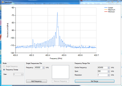
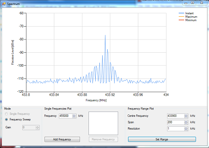
Here are some screenshots of the spectrum analyser graphical user interface. Please note that the levels shown have not yet been tested with proper equipment. Proper tests and calibration will be done in the next hardware iteration.
RS232 Spectrum Analyser
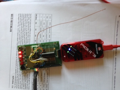
This project came from the idea that I needed a simple, light spectrum analyzer which could be easily interfaced to embedded applications. This design was a proof of concept which made use of an RFM22B radio module and a PIC16F690. A simple GUI was also constructed for initial testing purposes. Photos of the prototype can be seen below. Source code for the proof of concept can be found downloaded here:
The next post will contain some screen shots of the GUI in action.
