FPV Quadcopter Racing

After slipping into the world of quadcopters a few years ago, mostly for research purposes, I recently stumbled across a sport called FPV racing. This activity most commonly involves a small quadcopter equipped with a forward facing camera. The pilot then straps a monitor to his face and attempts to fly a designated race track. Think Red Bull Air racing, less expensive and less dangerous.

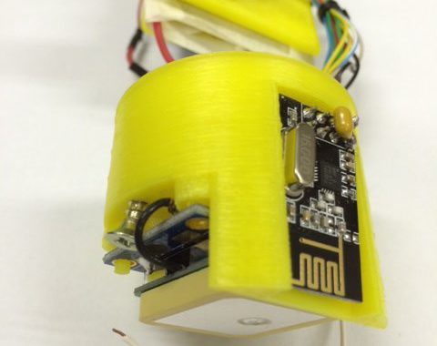
I built a 3D printed quadcopter based on the MHQ 2.0 on Thingiverse. All of the electronics were sourced from bandgood.com which made this probably the cheapest racer on the planet. Instead of buying the expensive Fatshark FPV goggles, I equipped myself with a Boscam transmitter and receiver along with Quanum foam goggles (Poor mans FPV option). In the end, I became comfortable with this setup with no regrets.

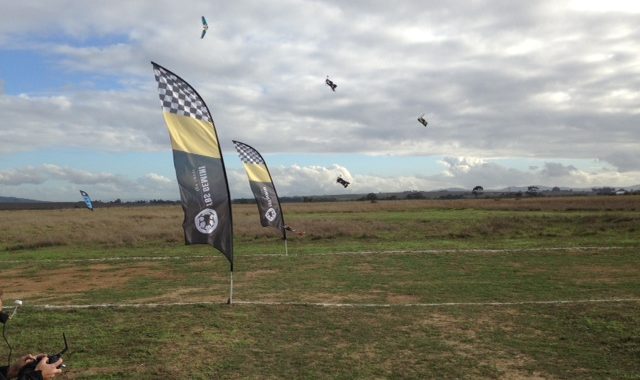
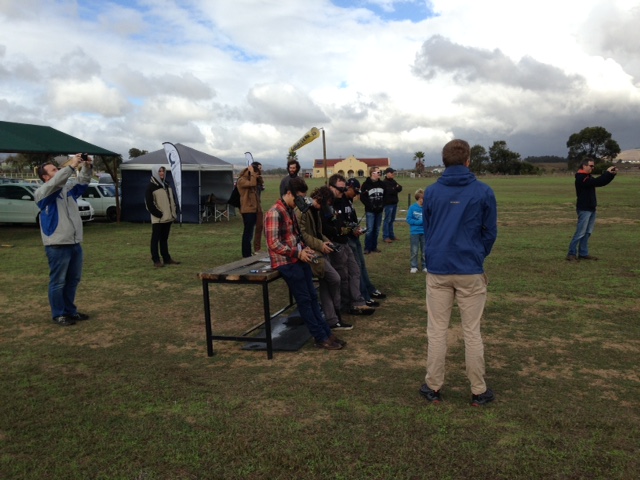
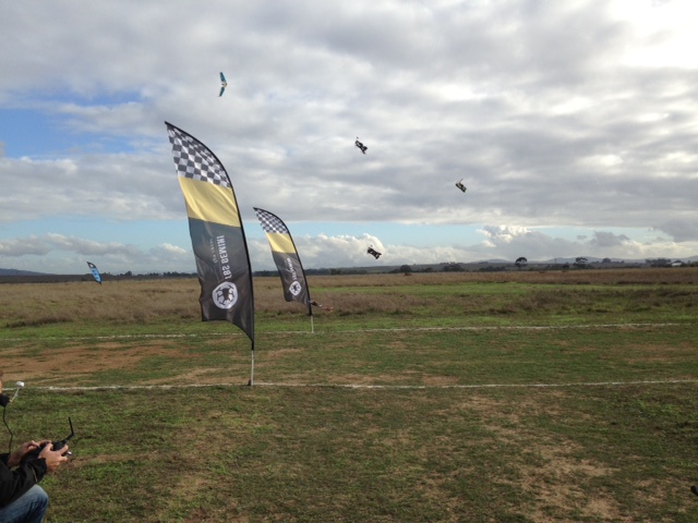
Yesterday I took part in the first race of the first official FPV racing competition in South Africa. My 3D printed underdog even made it past the first heat.

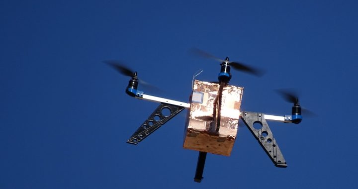
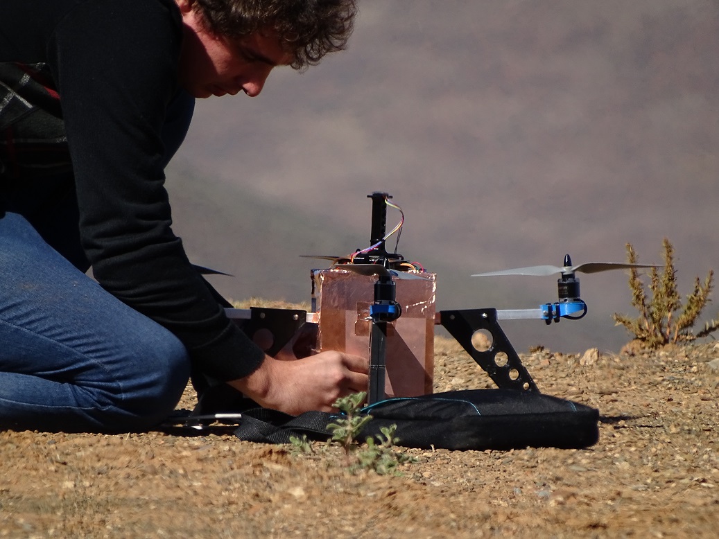
Below are some photos of my 3D printed FPV quad and South Africa first historical FPV race:

Pilots flying Race start image2

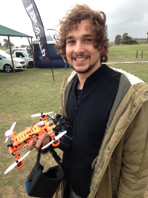
Smug face after coming second in my first heat.

The Intelligent Ski-Course

Last year I started building an intelligent ski-course, which was basically a set of buoy drones that would swim to there positions in a public river to form a ski course. This would then allow tons of interesting possibilities such as easy setup and effortlessly changing the shape of the course. Most of the project is documented on hackaday.io. As I am a very eager slalom skier in dire need of a course I would very much like to finish this project. However, I find myself without time working on finishing my PhD. I will one day restart my efforts, if anyone is interested in developing the project from where I left it, you are more that welcome, just keep me in the loop.

The state of the project:

  1. Most of the code has been written.
  2. The electronics for the buoy and base station has been mostly finalized
  3. 3D printed parts needs to be revised
  4. Propulsion system needs to be tested

Birth of FEMU 2.0

As part of my PhD research, involving the characterisation of the propagation environment at the SKA Karoo, time was spent developing a multi-copter RF metrology vehicle. A dramatic autopilot failure in our early prototype caused a the multi-copter to fly away forever. This event gave us a clean slate to do a full redesign upon what we have learned. One of the main problems with RF metrology using a multi-copter is the effect of the multi-copter itself on the measurement, which at this point has not been adequately addressed in research. Therefore, we set out to design a vehicle that could be appropriately de-embedded from a measurement.

The performance of antennas onboard these vehicles are in most cases unknown or assumed. These antennas have a specific characteristic pattern which could cause significant fluctuations in the measured signal, depending on its orientation. Even if the orientation was kept constant, the antenna patterns are sensitive to changes in metallic structures of the vehicle. An excellent example of this is the replacement of batteries after a flight. The replacement battery might have slightly different dimensions, position and will most certainly perturb some of the ubiquitous wires in the system.

Our approach was to shield all of the subsystems of the vehicle in a metallic enclosure. This shielding gave us a platform which had a predictable antenna pattern. Also, by closing the complex metallic environment, accurate antenna simulations have been made possible. Additionally, FEMU 2.0 also boasts a quasi-isotropic antenna pattern and a bandwidth of 260 MHz to 960MHz (See the paper for more information on this).

Hopefully, this will pave the way for RF metrology using multi-copters. If done correctly this could significantly speed up measurement time and deliver measurements that are spatially continuous. The entire vehicle has been constructed from 3D printed parts and local hardware supplies. The electronics, receiver and antenna systems can all be made available if another research group is interested in further developing the project.

Below are two images showing FEMU 2.0 during setup and measurement.

Setting up FEMU 2.0 before flight